Saturday, April 13, 2024

'64 BSA Lightning Rocket - Electrical

The wiring on the Lightning Rocket was in poor shape. The original wiring harness and switches remained while someone had started a 12V conversion. There was a Zener diode with its cooling plate mounted on the front end, a 12V ammeter in the headlight shell, and a 12V transistor block in the back. Pieces were disconnected in various places showing it was still a work in progress. Time for an intervention. 

The "as found" wiring on the Lightning Rocket. A mish mash of 6V and 12V bits. 

The electrical system in the '64 BSA was a bit funky if you ask me. In the days before NASA's space program there was not a good solution for voltage regulation in a size that worked well for a motorcycle. Fortunately Lucas had an answer. 

Their solution was a 6 volt system with a dual output alternator to keep things supplied with power. One winding powered the ignition system and another powered the lights. The lighting coil put out just enough juice to keep the lights on and with its limited output overcharging the battery was not an issue. The more power that came out of the alternator the brighter the lights became. If the battery was drained you could engage an AC current path from the alternator directly to the coils to fire it up. This was called an emergency starting circuit. I thought very briefly about keeping the 6 volt system but ultimately moved to 12 volts. 

Sorting out the wiring....6V to 12V......Trispark ignition...Podtronic unit. 

I decided to go with a reproduction 6V "made in England" wiring harness attached to a  high output Lucas alternator controlled by a Sparx box. A Trispark ignition is mated to Trispark coils.  The funky 6 volt bits will be unhooked and taped up. I also routed a ground line, using the unhooked 6 volt bits, to the headlight as the original system relied on frame grounding. This was problematic in the good 'ol days and not workable with a powder coated frame. A ground wire was also run to the tail light housing.

     The hybrid harness starting to take shape..... 

My solution for the Sparx box mounting....

 
All grounds came to this point. Powder coating on the frame was removed to leave bare metal between the ground post and one lower engine mount. 0.0 ohms resistance is measured.  


New old stock Lucas headlight switches and a repo ammeter. 

The Ducon was restored from original parts, repo gaskets and new wiring with original stripes. 

The reproduction harness was very authentic but missing all of the extensions. They were reproduced with soldered bullets and the correct Lucas wire to keep it all straight. 

A great tool for the toolbox, an accel coil wire crimper. 


The Trispark unit was wired and setup using a degree wheel as the '64 BSA did not have timing marks. My first time using this method....think I got it. 

Timing set with a degree wheel & indicator.  

The head on and plug wires connected. 

We have spark and lights which is a good sign. Onto the fuel & control systems. 

Tuesday, April 2, 2024

'64 Lightning Rocket - Engine Rebuild PT VI - Top End

The top end was tired on the LR to say the least. The cylinders were scored and the valves were significantly worn. A complete intervention was required. The cylinder was blasted bare and sprayed with VHT primer and paint. The head was chemically cleaned and walnut blasted. I considered vapor blasting for the aluminum parts on the engine but in the end I decided not to do so preferring to keep the casting glaze with which it departed the factory. To each his own I guess. Maybe vapor blasting will be used on the next build as I do respect the clean surfaces it produces.  

As found....a bit tired inside and out. 

Cleaned, painted, re-machined and ready to go

The cylinder was bored +.020 and Hepolite pistons were purchased for the build. Threads were chased and and the deck was ground to get it flat. The rings were gapped to specs greater than I have used before. Hepolite called out .012 - .018. I split the middle with .015.  

Rings being gapped for the new pistons and reworked cylinder. I use a fine file held in a vice to work both ends of the rings simultaneously. 

New guides were installed in the head which had its face skimmed. Kibblewhite black diamond valves were used and EV Engineering springs were installed. Elephant foot valve adjuster screws finished off the updates.           

Disassembly in process.....

Rebuilt and ready to go onto the power egg....

Copper annealed via MAP gas torch. I have not used head gasket sealer in the past but am giving Permatex copper spray gasket sealer a try this time. I have had issues with the oil holes leaking and am hoping this does the trick. 

Silicone gaskets work great if you don't overtighten them. 
Thanks Tennessee Real Gasket!

Torqueing down the head nuts with my home made offset spanner.
Ready for carbs, cables and final assembly. 


Friday, March 22, 2024

'64 BSA Lightning Rocket - Engine Rebuild PT V - Timing Side & Transmission


The plan was to install the engine in the frame without its heavy bits to make the process easier for the two old dudes performing the task.  The primary was rebuilt with its new parts staged on the bench ready to go including a large zip tie fed into its cavity to pull the alternator wires out. This makes a tough job relatively easy.  It's time to start staging and assembling the engine's timing and transmission components.  The oil pump and timing gears will be installed but the pump itself will go on later. 

Timing bits prepped and ready to assemble. The new SRM oil pump is a real beauty. 
I hope it works as good as it looks. What a shame to hide it behind a cover. 

The transmission bearings and seals were renewed even though they didn't look bad. The layshaft end play was checked by installing the mainshaft in the case and measuring to the workshop manual specs. A play of .002 was measured and will get that "butter smooth" BSA shifting I admire. The selector plate had very little wear on it and was reused with minimal cleanup. One shifter fork was worn and both were replaced as were the kickstart pinion gear and bushing. 

Worn and replaced.

New bearings, seals, shifter forks and kicker bits. Oiled and ready to assemble. 

Transmission bits assembled and ready to install

The last order of business on this side of the egg was to mount the kickstart spindle and its washer/spring from hell combo. I have fought this in the past but not as hard as on this one. A stiffer spring than others, I'm getting older and weaker, maybe my biorhythms were off???  Not sure but I stuck with it and was victorious. There is probably a factory tool I will never own to simplify this task. There has to be, otherwise I would call it a piss poor bit of engineering from a home mechanics perspective at least.  Too bad I don't drink beer anymore. This would be a perfect time for one or six. 

What a bugger of a job....until I figured out how to do it then it was a moderately difficult task. I'm putting a picture of my process here so I can reference it next time.....Push the washer on over the spring, put a hose clamp on the shaft to hold the washer in place and then pull the spring on with a hook tool all while trying not to impale yourself. The wrench was used to work the washer tab toward the spring hook. 

The '64 LR speedo drive is off of a gear mounted on the layshaft. Interesting. There are a series of gears you can swap to calibrate the speedo if you make drivetrain changes. There is also a badge on the outside of the case that denotes the installed speedo gear's ratio. 

Getting ready to assemble and prime the new SRM oil pump. Good lord that herringbone oil line is hard to find and expensive when you do.....


Turning stainless steel into CAD ....kinda....


Oil pump assembled and primed with oil running out the PRV mount per SRM's instructions.  A final check will be completed before starting the engine by pushing the bike down the road in gear with no spark plugs. Oil will flow into the tank through the return line if all is right . 

The SRM pump was very stubborn and did not prime easily. I turned over the rear wheel in 4th gear while my wife added pressure to the oil tank via my trusty propane air tank. 15 PSI did the job. 

Assembled and ready for the Trispark unit.....onto the ignition. 


Tuesday, February 20, 2024

'64 Lightning Rocket - Engine Rebuild PT IV - Primary

 The clutch was a bit knackered but still probably functional as it was found. The primary chain was stretched out as the "Wardmaster socket" under the adjusting pad would indicate. This has been a common occurrence found on old bikes when I tear them apart, although two out of three had lug nuts under them. Chains must have been expensive, hard to find. or not considered worth replacing "back in the day".

Tired but still serving its purpose.

"Wardmaster socket" taking up the slack. 

New bearings & rubbers ready to bring together.

My secret weapon for putting in cush rubbers, 
It makes a seemingly impossible job very possible. 

New bearings, friction plates, greased and ready to go. 

Sprockets fit without the chain to check alignment. All is good....

Primary parts ready for final installation & a timing disc setup being worked out. The final assembly will be done in the frame. On to the transmission & timing side.....

Timing/'TDC setup sorted. 
This will be revisited when the wiring is finished and the electronic ignition needs to be set. 

Assembly of the primary side was pretty straightforward. The rotor and stator went on passing the dollar bill test with no adjustments needed. The stator wires were fished through the case via the zip tie I had installed earlier. I am glad I did not forget that step as it is a real time saver 

Although I have never done this before I lightly oiled the clutch plates with type F automatic transmission fluid. I have always assembled them dry and they are usually oil soaked when removed. An expert in the field recommended lightly oiling them so I will give it a try. One thing that gave me fits was installing the clutch springs. Try as I might I could not get the retainer nuts to catch. After working a short while I decided to check the new springs I purchased to the originals. To my surprise they are .50 inches longer. The Lightning Rocket is specked for these longer springs although the standard Rocket springs came out of my clutch. I ordered a set of standard springs which are .25 inches longer than the originals but could not get them in either. Back to the original springs. The situation will be addressed at a later time if necessary.  Maybe a special tool?  Longer retainer screws?
Primary assembled and it's on to the timing side. 

Monday, February 12, 2024

'64 BSA Lightning Rocket - Engine Rebuild PT III - Bottom end Assembly

BSA used a ball bearing main on the drive side of their crankshaft from 62-65 with a plain bearing on the timing side. I have set the crankshaft end clearance on the later roller bearing cranks which is critical but had not assembled the ball bearing crank. The ball should hold the crank in location and there are no oil pressure concerns as on the roller bearing cranks which use a thrust washer on the timing side. The factory workshop manual shows the end clearance being set from .001 to .003 for the ball bearing crank which is the same as the roller bearing ones. The only reason I could see for this is to keep side load off of the ball bearing. If the factory says do it, do it I will. 
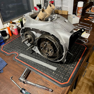
Crankshaft and cases were dry assembled with no shims to check end clearance. After measurement the necessary shims were added to get the .001-.003 spec. (shooting for .001 with .002 max) One note on crankshaft shim cups - Modern Hofmann ball bearings have a larger center than the originals. This requires the use of a shim cup & shims from a later roller bearing motor.

The rods were rebuilt with new wrist pin bushings and the big ends were machined to remove their oval shape. New shells, bolts and nuts finished off the rebuild. The crankshaft was assembled and checked for free movement once the rod bolts were torqued down. The case internals were installed making sure to get the camshaft and its breather assembly properly inserted.  Time to stick it together....

The bottom end and its parts ready to go. One pointer is to add the high gear and final drive sprocket before assembling the motor in the frame. Not really necessary but much easier in this order. Just trying to reduce the amount of swearing it takes to put one of these together......

Moving parts balanced......machining marks tell the tale. 

The crankshaft was shimmed and all parts were installed. Yamabond 4 was applied to the cases and they were bolted together. One final endplay check was performed after assembly and all was good. 

         
The bottom end ready to go into the frame. 

The crankcase was assembled with minimal components to keep the assembly light. This eases installation into the frame. The top end, timing side bits and the primary will be added with the engine in the frame. I took this approach on my Interceptor build with good results. I did not take this approach with my Hornet and struggled greatly with the weight of the unit. Lesson learned and on we go.......  

Frame prepped and anxiously awaiting the power egg....

Protection for the frame's new paint was added, all mounting bolts were ready to go in, and it was ready to receive the lump. The rear engine mount plates were loosely attached to aid installation. Working from the drive side the motor was installed with its front mount above the attachment point and the rear mount plates below theirs. One person was on each side of the bike to work the motor in place. The protection on the frame proved to be very necessary. 

Once the motor was in and all bolts were in the frame the lower mounts were checked for shimming. It is important to add washers to take up space between the motor and frame and not to pull the frame to the motor. (These shims are shown in the spares manual.) Bad vibrations will occur if this is not done properly. I also scrubbed the paint off of one lower mount so the engine will ground to the frame. Probably not necessary buy my electrical engineer friend says it is wise to do so I do.....

The motor is in and being built up. Adding the power egg without its heavy components worked well for two old dudes and will be my go to method. It was installed with the front mount high working it down and the rear mount a bit low working it up. This is opposite of what I have read but it worked very well.


Wednesday, July 26, 2023

'64 BSA Lightning Rocket - Carburetor Rebuild

I was pleasantly surprised that the Lightning Rocket still sported its original Monoblocs and they were in decent shape. The slide stop screws had been tightened a bit to much which put a crimp in the slides causing them to bind. Once the slides were out examination of the bodies showed they were in serviceable condition although new slides are required. Some of the fittings were rusted or had pliers put on them at some point in their life which grooved them up. One of the jet holder covers was seriously grooved. Why??!!!???!!

A bit crusty but mostly there....the original 389 Monoblocs

The slides were slightly galled and binding.

Plier marks are normal violations on these old carbs but why the grooves????

I have had good results with my ultrasonic cleaner. This takes the bits back to their core metal in most cases. I use Simple Green in the washer to assist in cleaning and have found high heat to aid in the process. I have soda blasted carbs in the past with good results but prefer the ultrasonic cleaner now that I have the process sorted.

My secret weapon...the Harbor Freight Ultrasonic

One supplement to my process this go around was to use CLR, which is a calcium and lime removing chemical, on parts with corrosion not removed by the ultrasonic. It is aggressive and should only be applied for a couple of minutes. This final step made my carb bodies look great. I finished them with a paste wax to keep the corrosion from coming back. This is my first attempt at this process and I will have to see how it plays out over time. The initial results are very good.

Parts cleaned up....ultrasonic...CLR.....wax...good to go....

Ready for assembly.....

The bores showed minimal wear so I decided to place new slides in them which worked well on my RE build. One of the foremost experts in the field says the bodies will last for 3 sets of slides if treated properly. While I have had carb bodies bored in the past I prefer not to have the expense if necessary and I do miss the choke which you sacrifice upon a re-bore. I have heard great things about the new Amal Premiers and will try them when replacements are necessary.

The bores required a slight cleanup to get the new slides to fit. High spots were sanded with 220 grit and a brake hone was used to get a tight slip fit. The mounting flange was also dressed flat with a file to correct a past mechanics over zealous wrenching. 

I chose to use the anodized slides for this rebuild. 
They are a pit pricy but I think the additional cost will be worth it. 
Ready to go, just need to set the float height.....shim if necessary. 

Time to sort out fuel taps, lines and air cleaners.......